Routing Basics
On this page
System Diagram
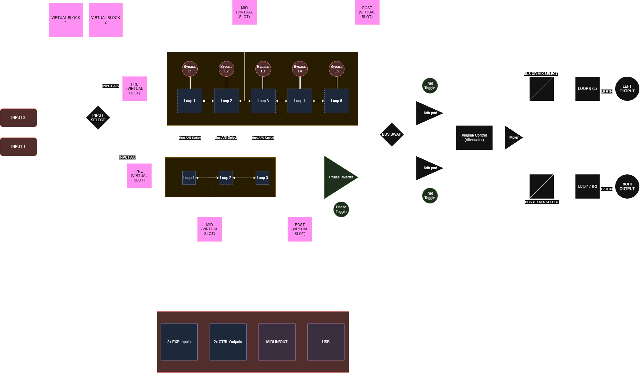
Buses and loop assignment
A bus is a signal path through Artemis. Effects placed along the same bus process the signal in series: the output of one feeds the next. Bus A and Bus B can run in parallel, processing separate signals or two copies of the same input before the output stage.
Choose each bus's source independently. One instrument can feed both buses by selecting the same input for each. Two instruments or a stereo source can use input 1 for one bus and input 2 for the other.
| Loop | Assignment |
|---|---|
| L1–L3 | Either Bus A or Bus B. |
| L4–L5 | Bus A only. |
| L6/L7 | Fixed stereo loop after the bus processing and mixing stages. |
The five mono loops are shared: a physical pedal can occupy one place in the route at a time. Moving its card changes the signal order without changing its cables. Use L6/L7 for a stereo pedal that should process the final left and right paths.
For the editor controls and examples, see Buses, inputs and outputs.
Virtual block placement
Virtual 1 and Virtual 2 insert digital processing into the analogue route. Each block contains its own pedal chain and optional amp and cab stages. Place a block at Pre, Mid or Post on either bus.
On Bus A, Mid is after slot 2; on Bus B, it is after slot 1. Pre is before the first slot, and Post is after the last slot. These positions refer to the reordered chain, not the rear-panel loop numbers. Bypassed slots still occupy their positions.
For example, OC-2 in A1 and Tube Screamer in A2 both feed a virtual block at Bus A Mid. Moving Tube Screamer to A3 places it after that block. If both virtual blocks share an insertion position, the signal passes through Virtual 1 followed by Virtual 2.
See Virtual block positions for the full table and Your first preset for a worked example.
Levels, mixing and bypass
Use the mixer to balance Bus A and Bus B, and to set the input and master levels of each virtual block. MIX at an output selects the combined bus mix; separate output routing preserves the individual paths. Check both the route and the levels when changing between these arrangements.
The input buffers can be switched together using the input-buffer control. Bypassing them changes the analogue input path and may change the level or tone. The output pads provide nominal −6 dB attenuation on the bus outputs before the mixer. Bus B's polarity control reverses that bus's signal polarity; compare it when combining two paths that sound unexpectedly thin.
Bypassing a physical loop skips its send/return path. Bypassing a virtual block uses the analogue through-path at that insertion point; bypassing one effect inside the block affects only that effect. Check transitions while playing before relying on an effect tail during a performance.
Save routing, bypass states, levels, expression assignments, CTRL states and the buffer choice with the preset. Song slot assignments are saved with the song. Stompbox Mode maintains its own bypass states and pedal order independently of songs.