Connections
On this page
Rear Panel Connections
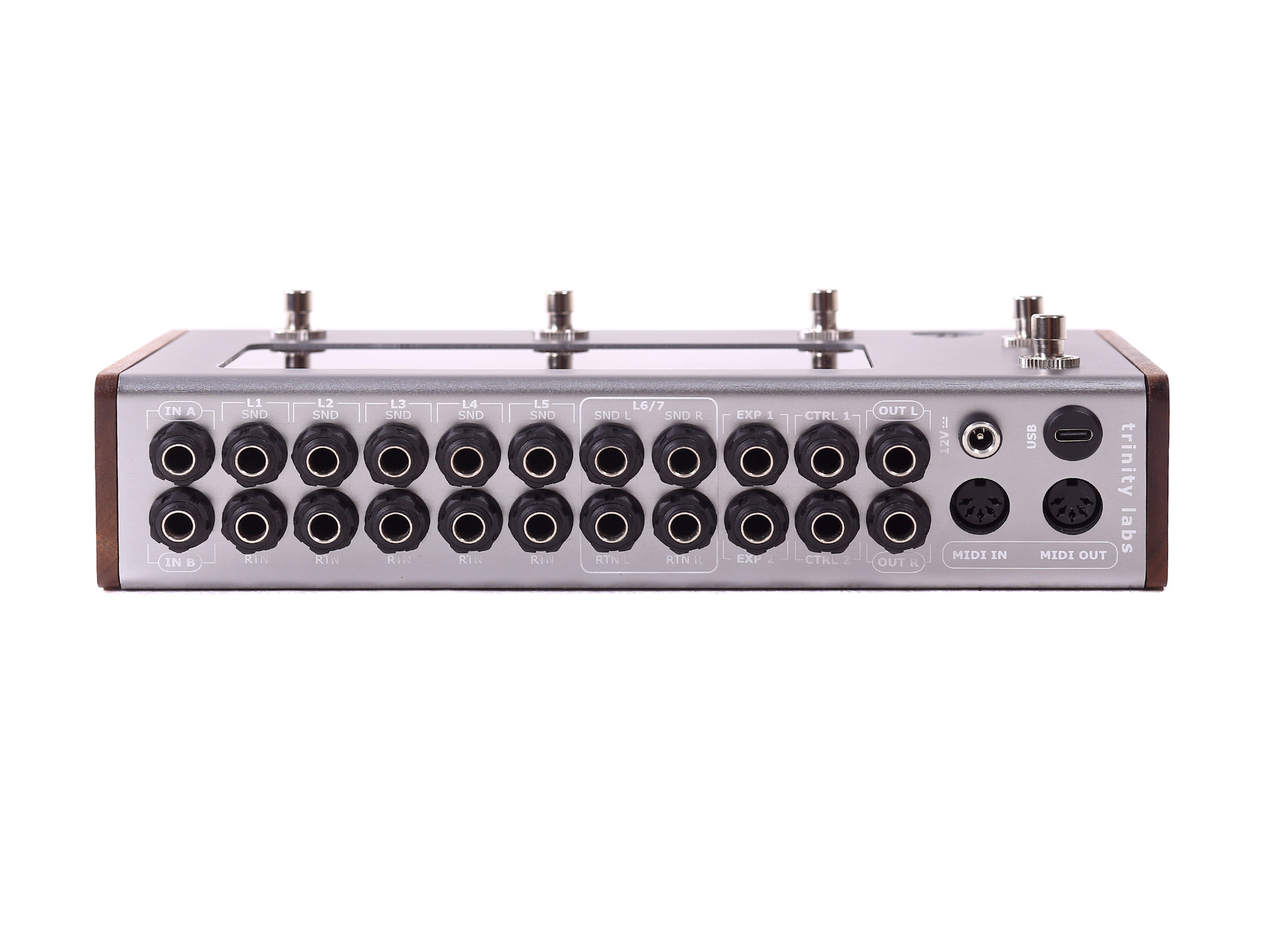
Rear view of Artemis. The guide below follows the connector groups from left to right as shown in the photograph.
| Panel label | Position | Function |
|---|---|---|
| IN A / IN B | Leftmost pair: A above B | Two audio inputs, routable to Bus A or Bus B. |
| L1–L5: SND / RTN | Five pairs, each with SND above RTN | Reorderable mono effects loops. Connect SND to the pedal's input and the pedal's output to RTN. |
| L6/7: SND L / SND R / RTN L / RTN R | Two pairs within the L6/7 outline: left channel on the left, right channel on the right; sends above returns | Fixed stereo effects loop. Connect the sends to the effect's left/right inputs and its left/right outputs to the matching returns. |
| EXP 1 / EXP 2 | EXP 1 above EXP 2 | Two TRS expression pedal inputs. |
| CTRL 1 / CTRL 2 | CTRL 1 above CTRL 2 | Two isolated relay-contact outputs for compatible amplifier switching or footswitch inputs. |
| OUT L / OUT R | OUT L above OUT R | Main left and right audio outputs. |
| 12 V DC | Above MIDI IN | Power input for the supplied 12 V DC, 2 A, centre-positive adapter. |
| USB | USB-C socket above MIDI OUT | USB device connection to a host computer. Artemis still requires its DC power supply. |
| MIDI IN / MIDI OUT | Lower-right DIN sockets: IN on the left, OUT on the right | MIDI IN receives messages from an external controller; MIDI OUT sends messages to connected equipment. |
Audio inputs, outputs and loop sends/returns use 6.35 mm (1/4-inch) TS connections. Expression inputs use TRS connections; CTRL outputs use TS connections.
The photograph labels the audio inputs IN A and IN B. These correspond to input 1 (IN1) and input 2 (IN2) respectively in the preset walkthroughs. The input numbers identify sockets; Bus A and Bus B identify the signal paths you route them to.
Example setups
For a mono instrument and amplifier, follow Quick Start. Each mono pedal connects between one loop's SND and RTN sockets.
For a stereo pedal in L6/L7, connect both channels as shown below. Feed OUT L and OUT R to the corresponding inputs of your stereo listening system.
Drawing signal path…
Text version of the diagram
flowchart LR
    SL["L6/7 SND L"] --> IL["Stereo pedal input L"]
    SR["L6/7 SND R"] --> IR["Stereo pedal input R"]
    OL["Stereo pedal output L"] --> RL["L6/7 RTN L"]
    OR["Stereo pedal output R"] --> RR["L6/7 RTN R"]
    AL["Artemis OUT L"] --> Left["Listening system left input"]
    AR["Artemis OUT R"] --> Right["Listening system right input"]
Enable the stereo loop in the preset. Use the output selectors to choose a mix feeding the stereo effect or separate left/right paths, as described in Selecting outputs and using the stereo loop. For a two-input setup, feed IN1 and IN2 from the source's left and right outputs and choose those inputs for the corresponding buses.
Expression, control and MIDI connections
Connect an expression pedal to EXP 1 or EXP 2 with a TRS cable. Houston provides calibration, response curves and smoothing in Expression / Control. Follow Expression calibration and assignment before assigning it to a preset. Software calibration adjusts the usable travel; it does not change the socket's electrical wiring. For pedal wiring and compatibility advice, contact support with the pedal model.
CTRL 1 and CTRL 2 provide isolated relay contacts through TS sockets for amplifier switching or footswitch emulation. Check that the amplifier accepts a relay-contact footswitch connection before connecting it. Ask support if its wiring or switching requirements are unclear. See CTRL outputs to save the required states with each preset.
Use standard 5-pin DIN cables for MIDI IN and MIDI OUT. MIDI carries control messages, so an external MIDI pedal still needs its own audio send/return connections. See MIDI connections and channel setup.
USB connection
The USB-C port connects Artemis as a device to a computer for file transfer. Use a data-capable cable and keep Artemis connected to its separate DC power supply. Connect the computer directly to Artemis; this workflow does not use a USB memory stick.
- Save your work in Houston and return to Launchpad.
- Open the relevant transfer guide: NAM, IR, Recordings or Updates. General transfer controls are also available alongside the file/storage controls.
- Connect the cable and enable USB transfer when prompted. The computer receives the ARTEMIS drive.
- Copy files into the folder specified by the guide, or copy recordings and backup archives to the computer.
- Wait for copying to finish, then safely eject the ARTEMIS drive on the computer.
- Finish the transfer in Launchpad so Artemis can use its storage again.
While the computer owns the drive, Launchpad prevents local file operations and application launches that need that storage. Ejecting on the computer and finishing the transfer on Artemis are both required. This is a file-transfer connection; use the DIN ports for the MIDI procedures in this manual.